
• Shortest-path power transmission design

    The bed ribs are manufactured as V-shaped ribs to achieve a more rigid machine and enhance precision. The power transmission via the shortest path between the guideways and the anchor bolts is designed to meet the demand for a sturdier machine.

  • Double-walled bed design

    A double-walled structural design has been adopted to maximize rigidity and minimize heat-induced elongation and thermal expansion.

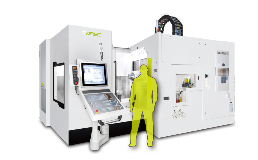
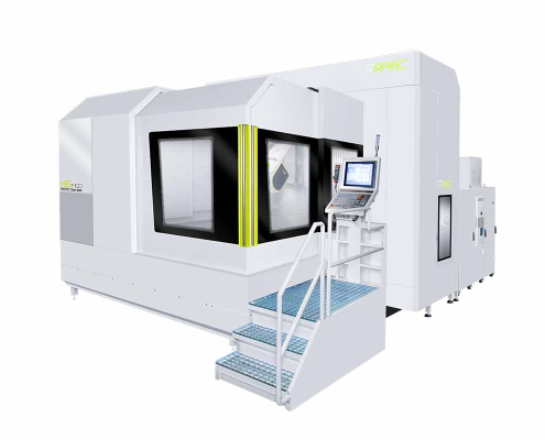
TT APEC HS1400

5-Axis Horizontal Machining Center

A specialized machine for the aerospace industry, thanks to its proficiency in machining superalloys.

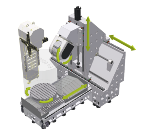
  • Rigid T-shaped bed.

  • Symmetrical, double-walled bed design.

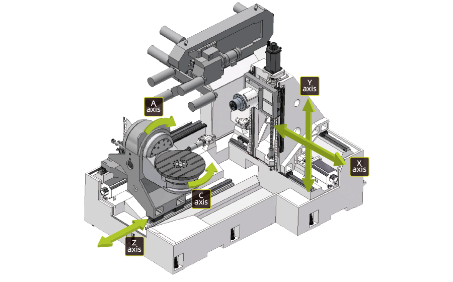
  • High-speed X, Y, and Z axes driven by ball screws.

45° Bed Design

  • Designed at a 45° angle, the bed combines with a fork-type head to enable machining across wider angular ranges.

Shortest-Path Power Transmission Design

  • The ribs of the base are manufactured as V-shaped ribs to achieve a more rigid machine and enhance precision. The power transmission via the shortest path between the guideways and the anchor bolts is designed to meet the demand for a sturdier machine.

Specifications

  • X, Y, Z Axis Travels
  • X, Y, Z Feed Rate
  • Table Dimensions
  • Max. Turning Diameter
  • Maximum Load
  • B-Axis Torque
  • B-Axis Max. Working Diameter
  • B-Axis Max. Rapid Traverse Rate
  • B-Axis Clamping Torque
  • Tool Taper
  • Spindle Speed
  • 1.800 mm x 1.250 mm x 1.320 mm
  • 50 m / dak
  • Ø 1250 mm
  • Ø 1800 mm
  • 3200 kg
  • 3.100 Nm / 5.190 Nm
  • ± 360 ° (Sürekli)
  • 65 rpm
  • 15.000 Nm
  • HSK-100A
  • 12.000 rpm
  • Spindle Power (S1 Max.)
  • Spindle Torque (S1 Max.)
  • Positioning Accuracy
  • Repeatability
  • A-Axis Torque (S1/S6)
  • A-Axis Clamping Torque
  • Tool Capacity
  • Max. Tool Length
  • Max. Tool Diameter with Adjacent Tools
  • 50 / 76 kW
  • 200 / 302 Nm
  • X/Y/Z 0.010
  • X/Y/Z 0.008
  • 1.192 / 1.980 Nm
  • 4.000 Nm
  • 40 ad.
  • 450 mm
  • Ø 125 mm

45° degree saddle design

The saddle is designed with a 45-degree angle and matched with a fork-type head, the machine can achieve more angles of cutting range.

THE SHORTEST FORCE FLOW BED DESIGN

The ribb ed s tructure of the b ottom b ed is V-shaped ribs to make the s tructure s trong and ensure pro cessing s tability. The shor test configuration of the force flow between the guide rail and the anchor bolts meets the demand for high rigidity.

Double-wall structure designed column

Increase the structure rigidity and to minimize the
possibilities of thermal deformation.

The base structure is optimized through Finite Element Analysis (FEA)

The X-axis adopts a high and low r ail design. The L 1
size is larger than other indus try and driving the
center of gravity is closer to the tool tip point, which
improves rigidity and stability. It is suitable for
processing difficult-to-cut materials and achieves
perfect cutting dynamic characteristics.

Contact